For food factories processing sticky, viscous, or irregular products—like capers, fresh meat chunks, mustard, or pickles—weighing has always been a headache. Traditional combination weighers struggle with product sticking to hoppers (causing underweight packs and cleaning delays), while manual weighing can’t keep up with production speed and wastes raw materials. But UUPAC's Dimple 14 Head Computer Combination Weigher is designed to solve these pain points. This blog dives into its sticky-product-specific design, core features, real-world applications, and why it's a must-have for food manufacturers dealing with hard-to-handle materials.
What Is a Dimple 14 Head Computer Combination Weigher?
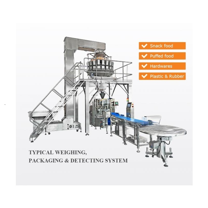
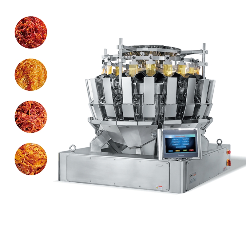
UUPAC's Dimple 14 Head Computer Combination Weigher is a specialized automated weighing system built for irregular, poorly fluid, and sticky food products. Unlike standard 14-head weighers, it features a unique "dimple" scraper hopper design (1.3L capacity per hopper) that prevents sticky materials from adhering to surfaces. Paired with 14 independent, computer-controlled weighing heads and a high-precision control system (MCU/Siemens PLC), it delivers fast, accurate quantitative weighing—even for products that typically clog or stick to regular equipment.
With a weighing range of 5-600g per batch and ±0.1g accuracy, it's ideal for small-to-medium production lines (up to 60 packs per minute) that process sticky foods, balancing efficiency with the precision needed to avoid waste and meet quality standards.
Why It's a Major Improvement for Sticky Food Processing?
Sticky products like fresh meat, mustard, or pickles demand three key capabilities from a weigher: anti-stick performance, easy cleaning, and stable accuracy. The Dimple 14 Head Computer Combination Weigher checks all three boxes—here's how:
1. Dimple Scraper Hoppers: No More Sticking or Clogging
The biggest innovation of this weigher is its 1.3L dimple scraper hoppers. The hoppers feature a textured "dimple" surface and built-in scraper mechanisms that reduce contact area between sticky products and hopper walls (preventing mustard, fresh meat, or capers from clinging), and automatically scrape residual material during each weighing cycle—ensuring no leftover product affects the next batch's accuracy.
A pickle factory in Shandong previously used a standard 14-head weigher and spent 2 hours per shift manually scraping hoppers to remove stuck pickles. After switching to UUPAC's dimple hopper model, cleaning time dropped to 20 minutes per shift—freeing up labor for other tasks and cutting downtime by 30%.
2. IP65 Waterproof Design: Easy Cleaning for Food Safety
Sticky food processing lines require frequent cleaning to meet hygiene standards (e.g., HACCP, FDA). This weigher's IP65 waterproof rating means all critical components (including the control panel and load cells) resist water and chemical cleaners. Plus, it has a "one-key clean function" that keeps all hoppers open—no need to disassemble parts to reach hard-to-clean areas.
For a fresh meat processing plant, this translates to faster cleaning cycles (30 minutes instead of 1 hour), no risk of water damage to internal electronics (a common issue with non-waterproof weighers), and compliance with strict food safety regulations—avoiding costly audits or recalls.
3. ±0.1g Accuracy: Cut Waste & Avoid Customer Complaints
Sticky products are prone to uneven weighing—too little and you risk regulatory fines; too much and you waste expensive ingredients (like fresh cuts of meat or imported capers). The Dimple 14 Head Computer Combination Weigher uses two key technologies to maintain precision: special high-standard load cells that detect even tiny weight variations (down to 0.1g) to ensure each batch hits the target weight, and a professional A/D card that converts weight data into digital signals quickly and stably—avoiding errors caused by product stickiness or vibration.
Ideal Applications: Which Sticky Foods Work Best?
This weigher is tailored to food products that challenge standard weighers. For capers (pickled) with a target weight range of 10g–30g, it reaches 55–60 packs per minute, and its dimple hoppers prevent brine-induced sticking. For fresh meat chunks (50g–200g), it operates at 40–50 packs per minute, with the IP65 waterproof design handling meat juices effectively. Mustard (paste) in 5g–50g portions sees speeds of 50–55 packs per minute, thanks to high-precision load cells that avoid overpacking. Pickles (sliced or whole) in 30g–100g batches run at 45–50 packs per minute, and the scraper mechanism eliminates residual pickles. Even powdered sugar (prone to clumping) in 15g–80g amounts hits 50–60 packs per minute, as anti-noise PVC parts reduce clump-related errors.
Why Choose UUPAC's Dimple 14 Head Computer Combination Weigher?
Beyond its sticky-product design, UUPAC adds value with practical perks that save time and money. It's ready in stock—no waiting for production; order today and ship from Shanghai, Ningbo, or Guangzhou ports within 3 days. The modular electronic system means if a part needs replacing (e.g., a hopper or sensor), costs stay low and downtime is short (usually under 4 hours). The HMI lets you set different access levels (e.g., operators can't change weight parameters), preventing human error. Plus, UUPAC sends technicians to your factory to train your team on operation and cleaning—no extra fees.
Conclusion
If your food factory struggles with weighing sticky, irregular products, UUPAC's Dimple 14 Head Computer Combination Weigher isn't just an upgrade—it's a solution to cut waste, speed up production, and stay compliant. Its dimple hoppers, waterproof design, and precision technology are built for the unique challenges of sticky food processing, while its compact size and modular maintenance fit small-to-medium factories.
Ready to see it work for your product? Please contact UUPAC today for more information. Stop letting sticky products slow you down—choose a weigher that's designed for your needs.