Gas Seals vs Wet Pressurized Seals
Given increasingly stringent environmental regulations, gas sealing technology remains crucial for ensuring the safe, reliable, and sustainable operation of pumps, mixers, and rotating equipment. Dry gas end-face lubrication offers significant advantages, ensuring high product purity and zero emissions. This technology has effectively reduced hazardous emissions over the years.
It is estimated that over the past 31 years, approximately 105,000 non-contacting gas seals have been sold, with an average service life of six years. This represents a potential avoidance of approximately 272.2 million pounds (123.4 kg) of toxic releases through zero-emission technology.
Maximum Availability Control Technology (MACT) is a key tool in achieving these goals. The California Air Quality Management Department (AQMD) estimates annual emissions from chemical/refining process pumps at 432 pounds, while the latest data from the US Environmental Protection Agency (EPA) suggests up to 2,200 pounds per pump. As early as 1993, this technology was proven to save $500 per seal (at an electricity cost of 6 cents per kilowatt-hour). Today, with energy costs rising to 10–16 cents per kilowatt-hour, the annual energy savings per seal have reached $1,350.
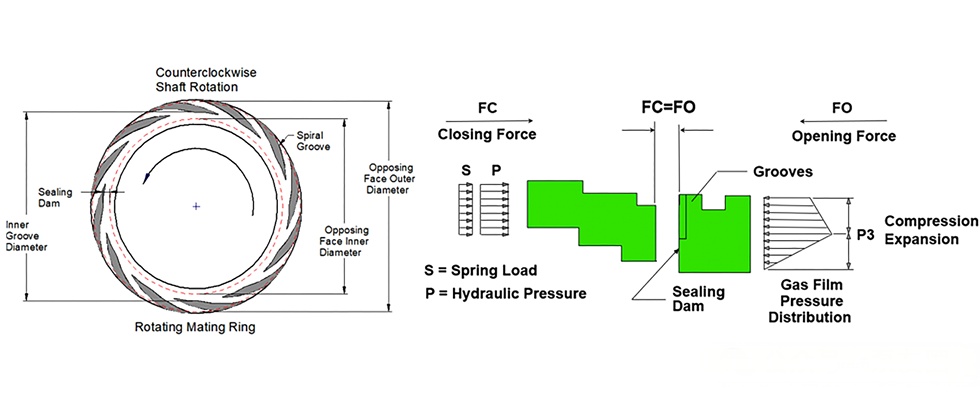
Figure 1 Energy Consumption Comparison between Gas Seals and Wet Seals
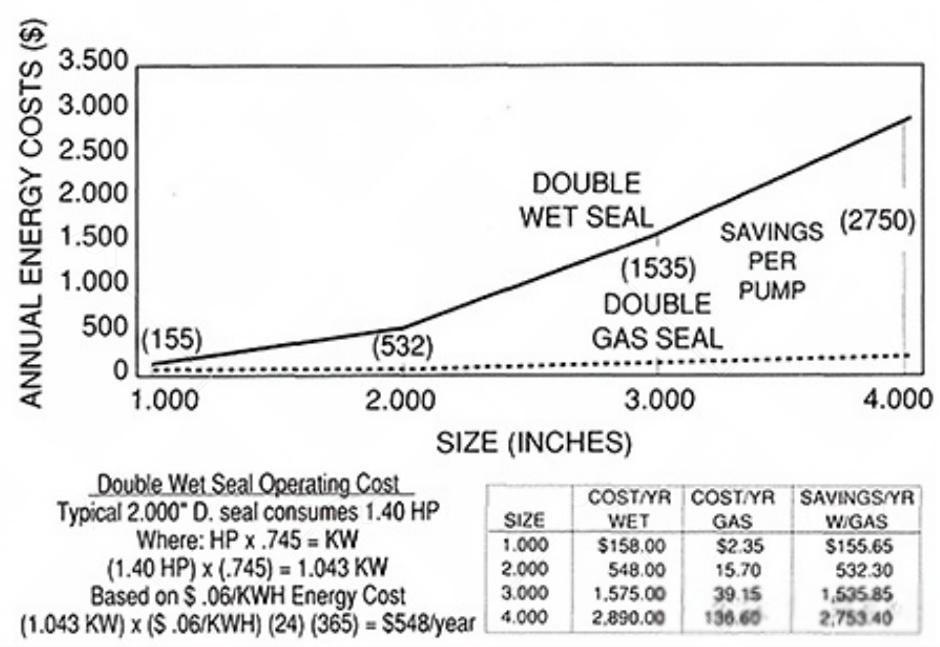
Figure 2. Typical spiral groove surface pattern and pressure gradient generated by the grooves
A variety of sealing arrangements are currently available to reduce emissions. The following is a ranking of their ability to control emissions on rotating equipment, listed from best to worst:
● Dual pressurized, non-contacting gas seal
● Dual pressurized liquid seal
● Dual pressureless seal with liquid barrier seal
● Dual pressureless seal with dry-running contacting/non-contacting barrier seal
● Single seal with sleeve
● Single seal
● Stuffing seal
The Evolution of Sealing Technology in Fluid Pumping
Early fluid pumps used fiber packing coated with wax or graphite to seal shaft leakage, but this method generated heat and shortened service life. Perforated lantern rings were introduced to improve lubrication and cooling. Good lubrication effectively extends the service life of sliding surfaces.
These limitations led to the development of mechanical shaft seals, which require effective lubrication. Advances in tribology and fluid engineering have further optimized seal lubrication systems. Manufacturers have designed pressure- and wear-resistant end face structures, some of which even utilize deformation to enhance lubrication and reduce wear. Ground and polished seal faces offer excellent pressure, friction, and wear resistance.
Liquid seal face lubrication is widely adopted due to its stability under high pressure, heat resistance, and compatibility with process fluids.
The Development of Spiral Groove Technology
Dutch tribology professor Evert Muijderman pioneered the use of a repetitive groove pattern in ultracentrifuges. This technology later evolved into mechanical seals and was first used in pumps over 30 years ago.
The non-contact function is achieved through a pattern on one sealing surface. As the shaft rotates, the pattern separates the sealing surfaces, eliminating friction. An inert gas (such as nitrogen) is used as a barrier gas, at a pressure 20 to 30 psi above the process pressure, achieving zero emissions.
Spiral grooves typically feature logarithmic spiral grooves machined into one sealing surface (usually made of a harder material). As the shaft rotates, gas is drawn into the groove, compressed by viscous shear, and then expands at the seal dam, creating a separation gap of several microns between the two sealing surfaces. The static pressure effect during downtime helps minimize seal surface damage.
The earliest spiral groove seals were unidirectional grooves on the outer diameter of a fixed end face. Because process pump speeds are much lower than those of turbo compressors (only 1200 to 3600 rpm), stronger materials, advanced groove designs, and lower spring loads and O-ring friction are required to improve seal face separation efficiency.
Application of Spiral Groove Technology
In 1992, a polymer manufacturer successfully implemented a non-contacting dry gas seal in a pump, effectively protecting product purity and the environment. Over the past 30 years, this technology has been widely used in equipment such as pumps, mixers, fans, and blowers, operating under a wide range of speeds, pressures, temperatures, and solids loadings.
Figure 3 shows the first dual-pressurized non-contacting seal installed in a large-bore centrifugal pump. Figure 4 illustrates a non-contacting gas seal suitable for ANSI and DIN standard bores, featuring a spiral-grooved mating ring and an inert barrier gas. Figure 5 shows the same seal configuration with the addition of a drain for process conditions up to 30% solids loading.
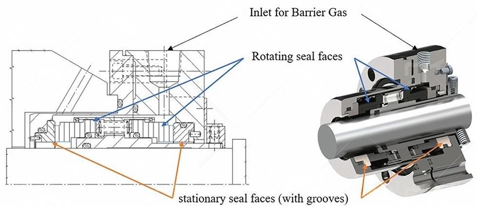
Figure 3: The first dual-pressure, non-contacting seal installed on a process pump, circa 1992
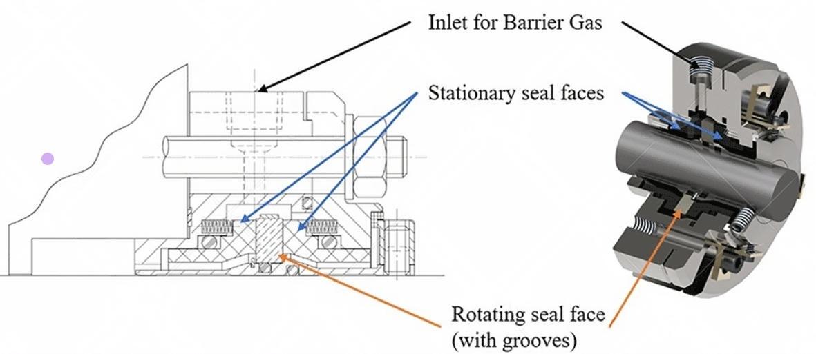
Figure 4: Gas-lubricated, non-contacting seal for a standard bore seal cavity
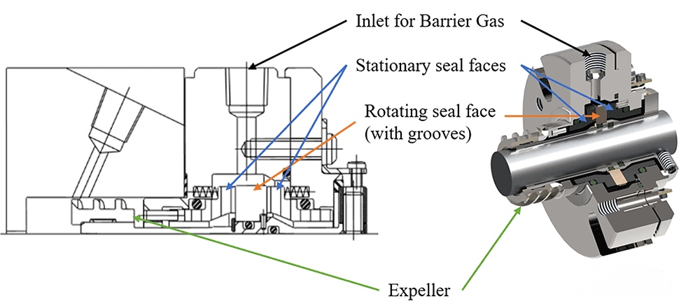
Figure 5: Gas-lubricated, non-contacting, standard bore seal cavity
This technology was subsequently expanded to mixers and containers, widely used in the pharmaceutical, food processing, and petrochemical industries to ensure product purity. Designers also developed spiral grooves on the carbon primary ring to accommodate low-speed and high-shaft runout conditions, achieving both hydrodynamic and hydrostatic lift.
Twenty years later, seal designs were further upgraded to meet the demands of higher pressures and solids-laden processes. Figure 7 shows a new seal designed for large-bore ANSI pumps, offering enhanced solids handling and performance.
The latest development is a gas seal suitable for high-temperature service (up to 800°F / 425°C). The metal bellows seal, shown in Figure 8, provides spring force, accommodates axial displacement, and effectively transmits torque. The bellows acts as a dynamic sealing element, supporting a variety of secondary seal combinations. The seal features pressure balancing and reverse operation to prevent accidental release of process fluids.
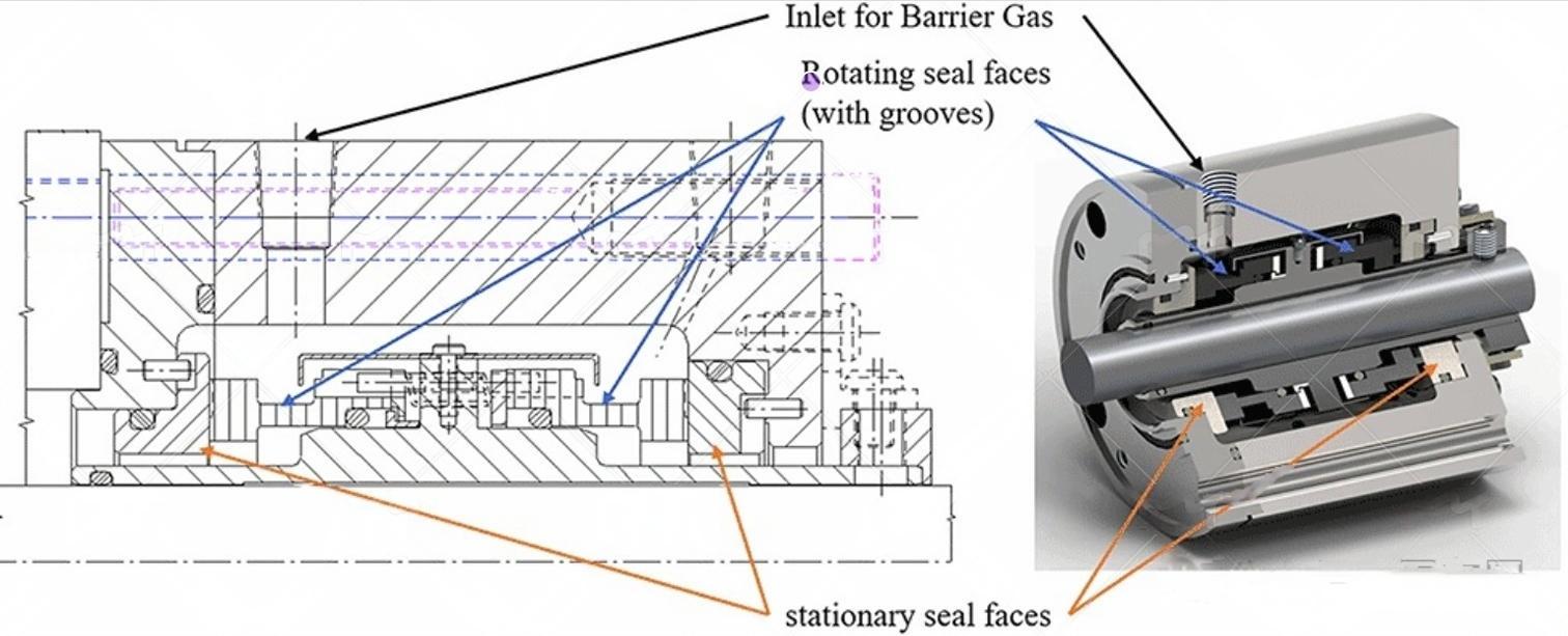
Figure 6: Gas-lubricated, non-contact mixer
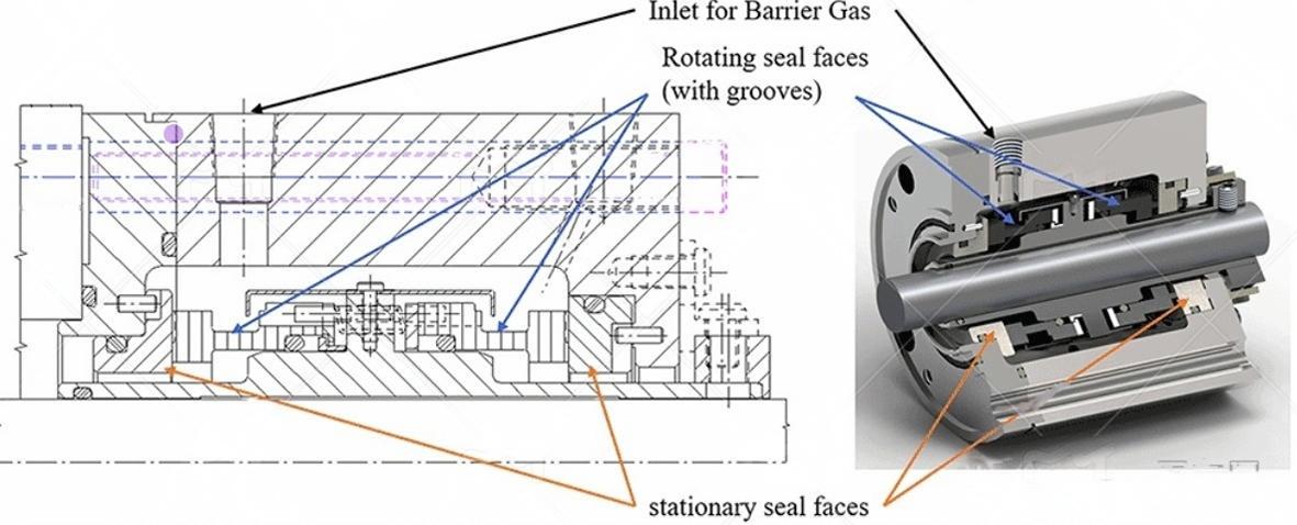
Figure 7: Gas-lubricated, non-contact seal for high pressure and solid materials
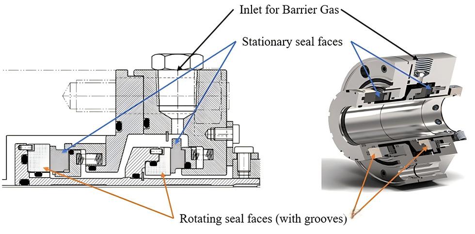
Figure 8: Gas-lubricated, non-contact seal for high-temperature service
Application of Spiral Groove Technology
In all pressurized dual seal configurations, the barrier fluid pressure is higher than the process pressure being sealed. The dual gas seal differs from other pressurized seal configurations in that it does not rely on fluid circulation between the seals, but instead relies on an external inert gas source to pressurize the seal chamber. According to API 682, Fourth Edition, the corresponding piping plan for this type of seal is Piping Plan 74. Figure 9 shows a basic schematic diagram of this plan.

Figure 9 API Piping Plan 74 - API 682 Fourth Edition
The sealing system works by allowing fluid to flow from a high-pressure area to a low-pressure area. Mechanical seals minimize leakage through sealing faces and O-rings while maintaining a small gap to prevent overheating. This gap allows the high-pressure fluid to flow to the atmosphere. Dry gas barrier seals use a regulated inert gas (such as nitrogen) at a pressure 30 to 50 psi above the process pressure to achieve a seal.
Nitrogen is most commonly used as the barrier gas due to its compatibility and affordability. Nitrogen is typically supplied from a pressurized nitrogen line or from a nitrogen cylinder, but this is less reliable. If nitrogen pressure is insufficient, a gas booster can be used.
The control system must regulate pressure, filter the barrier gas, and monitor pressure and flow to prevent overpressure. Due to the extremely small gap between the sealing faces, the gas must be filtered to less than 1 micron. A flow meter monitors the gas flow, while the API Plan 74 panel is equipped with a transmitter to continuously monitor the seal status. The key parameter is the barrier gas pressure supplied to the seal.
Advantages of Gas Seals for End Users
Despite the numerous advantages of gas seals in pumping equipment, there are still some misunderstandings regarding the choice between wet and dry dual pressurized seal configurations. Wet pressurized seals rely on a liquid barrier fluid (such as API Plans 53A/B/C and 54) for lubrication and cooling, while dry pressurized seals use gas and require minimal preconditioning.
Cost Comparison
The base cost of wet and dry seal cassettes is similar. Wet seals require nitrogen, clean fluid, electrical wiring, cooling water, and power for the pump and fan; dry seals, on the other hand, rely primarily on nitrogen and electrical connections; if pressurization is required, they only require power to the nitrogen booster.
Barrier Fluid Compatibility
Wet seals have higher compatibility requirements for liquid barrier fluids, which may affect process quality. Dry seals use inert nitrogen, which generally does not pose compatibility issues.
System Monitoring and Maintenance
Wet seals require regular replenishment of barrier fluid and maintenance of the heat exchanger. Dry seals require monitoring of barrier pressure and a backup nitrogen source to ensure system reliability. Although high gas flow rates with dry seals require investigation, continued operation is generally acceptable as long as the barrier pressure remains stable.
Energy Consumption and Heat Control
Compared to gas seals, wet seals consume more horsepower and generate more heat. Gas seals also experience lower temperature rises and lower energy consumption. According to statistics, wet seals consume approximately 1,300 kWh of electricity and release 2 tons of carbon dioxide (CO₂) annually, while dry seals consume only 350 kWh and release 0.54 tons of CO₂. Over the past 31 years, approximately 105,000 gas seals have been installed worldwide, with an average operating life of six years per system, resulting in cumulative energy savings of 8.6 million kWh, equivalent to the total electricity consumption of the residents of Houston, Texas.
Installation Flexibility
Gas seal systems eliminate the need for complex fluid circulation, allowing for greater flexibility in the installation location of control and monitoring instruments. In contrast, wet seals require closer installation to the equipment to reduce piping losses. This flexibility is particularly useful in equipment retrofit projects, facilitating maintenance and repairs.
Compared to traditional liquid-lubricated contact seals, non-contacting dry gas seal technology significantly reduces fugitive emissions from process pumps, saving thousands of tons of toxic waste and eliminating the need for cooling water. Furthermore, this technology reduces parasitic power losses, significantly improving energy efficiency and saving approximately 2 tons of CO₂ per pump annually. Furthermore, improved mean time between repairs (MTBR) and equipment reliability offer significant operating cost advantages.
Non-contacting dry gas lubricated seal technology remains an ideal solution for achieving emission reduction goals and improving equipment reliability. As with any advanced technology, its application must be scientifically sound and tailored to local conditions. Proper selection and implementation of this technology not only improves equipment performance but also delivers significant economic and environmental benefits.
