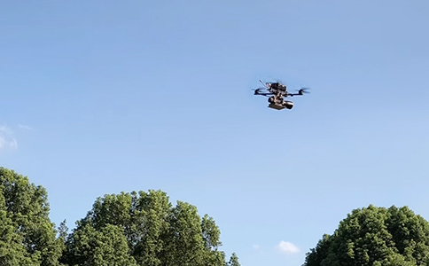
With the rapid development of drone technology, its application in various fields is becoming more and more widespread, and the share of consumer-grade drones is high, and as drones fly into the life, the phenomenon of flying indiscriminately occurs from time to time. Nowadays, the Interim Regulations on the Administration of Unmanned Aerial Vehicle Flights stipulate, which are no-fly zones. However, it is understood that even with the promulgation of the new regulations, there are still many flyers who do not have permission to fly drones on a trial basis. In response to this situation, the relevant units are required to follow the detection and countermeasures drone equipment, so as to protect the safety of airspace.
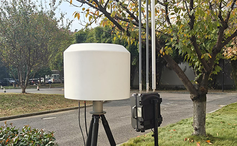
Equipped with an external ultra-wideband antenna, the Drone Detection and Warning Instrument is capable of providing acoustic, optical and electrical warnings for common civilian drones on the market by virtue of its recognition of the spectral characteristics of drones. Even in a complex electromagnetic environment, its false alarm rate is relatively low. The instrument can be used to collaborate with portable drone countermeasures equipment for mobile duty, so as to detect black-flying drones in a relatively short period of time.
Product Features
Detect all models:
Adopting digital-analog hybrid technology, with built-in spectrum library of various models' characteristics, it can realize long-distance detection of common consumer-level DJI, DaoTong and other models on the market by detecting the spectrum signals of drones.
Long detection distance: equipped with a high-gain receiving antenna, the warning detection distance is far.
Detection log: with drone log export function, it can record and export the detected drone brand, time and frequency and other information.
Power on operation
Turn the power on and volume knob clockwise to turn on the device. When the knob is turned clockwise to zui, the alarm volume is high.
Display Interface.
When a drone is detected, the screen will display the drone's model, frequency meter field strength information, and at the same time, the status indicator will change from green to red, while playing an alert tone. Read "How Drone Countermeasures and Detection Can Protect Low Altitude Safety".
When the battery power is too low, the battery icon will turn red and keep flashing, at which time the battery should be charged or replaced in time.
After detecting the drone, you can choose portable drone countermeasures equipment to dispose of the black-flying drone.
Choose to use Portable Drone Countermeasure Equipment to block the communication link between the drone and the remote control by transmitting electromagnetic waves, so that the drone is out of control and unable to perform the intended task. Common jamming bands include 2.4GHz and 5.8GHz, which are the exact communication frequencies commonly used by most civilian drones.
Warm Tips:By choosing drone detection countermeasures equipment, you can directly obtain information about nearby drones and take immediate countermeasures based on the detected drones. For drone detection and countermeasures equipment, if you have any questions about purchasing, you can directly contact our customer service of Nanjing Clairvoyant Aviation Co.